

Last week's post covered setting up your preferences and layers in Illustrator. In this post, I will cover drawing basic outline shapes, then I will do a post on finishing off the schematic, covering things like adding curves and alignment.
I like to draw schematics from an overhead flat shot of the garment. It means that the drawing will give a good impression of the shape of the piece, without having to spend ages drawing lines to scale from measurements. To get a good outline photo, make sure that you take the picture from directly overhead. The garment in the example below is the Droplet Bolero from A Stitch in Time vol 2.
If you can't find one of the palettes I refer to, look for it in the Window menu, and once it is open, you can drag and drop it onto the right hand side of the screen.
The image will be built from the bottom upwards, starting with the main outline of the piece (details like front openings or front neckline can be added later).
Unlock your bottom layer (in my case it is called Scan) by clicking on the padlock icon on the Layers palette. Click on the layer so that it is highlighted in blue, and therefore active. Then choose Place... from the File menu and select the image file for the photograph you wish to use.

Use the black arrow (the Selection Tool) to resize the photograph. Holding down shift while you do so will ensure that the proportions of the picture are retained. If you also hold down the alt key, then the photo will stay centred in the same place. Resize the photograph so that it sits comfortably on the artboard, with space around it for arrows and measurements.
Once you are happy with the size, then lock the Scan layer. Now you won't be able to move the photograph by mistake. If you need to adjust it later, you will simply need to unlock the layer again before making any changes.
Now unlock the layer where you plan to draw the outline shape of the garment. Click on the layer so that it is highlighted in blue. Make at this point that you have selected Snap to Grid in the View menu.

Then choose the Rectangle tool from the palette of options on the left of the screen. If you can't see a plain rectangle, the it might be hiding underneath one of the other shape tools (ellipse, polygon, star, rounded rectangle etc...). Just click and hold on the tool button to see the other options and select the rectangle tool.
Draw a rectangle over the body of your garment.

Then select the fill by making sure that the filled box is to the front on the toggle on the left-hand side of the screen.

And choose a fill colour from the Swatch palette (or use the Colour palette if you want more control of the exact shade). I usually fill the outline shape with white. This means that if your schematic is placed onto a coloured section of page, the outline shape will have a white background. If you have no fill (the red slash through a white box), then the schematic will have the same background colour as whatever it is placed over.
Then click on the stroke toggle, so that the outlined square comes to the front.

You can now choose the outline for your schematic. You select the colour you want from either the Swatch or Colour palettes as before. Then you also need to select how thick your outline line will be, and whether it will have sharp or rounded corners. You make these choices on the Stroke palette (the button with different types of horizontal line) on the right-hand side of the screen.
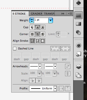
I use a 1 pt line thickness with rounded corners and ends. Play around with the options to see what effects you like best.
To make the outline into your desired shape, you will need to add some more anchor points (unless you want to draw a schematic of a rectangle of course). Anchor points are the handles at the corners of your shape, and by adding more, you can make a more complex shape. Make sure that your rectangle is selected and you can see the selection outline and small square handles at the corners (in the picture above, showing the rectangle, these are shown in blue). Choose the Add Anchor Point tool from the tools on the left of the screen. It may be hidden under the Anchor Point tool, in which case click and hold to choose from the other options available. The tool looks like a fountain pen with a small plus sign beside it.

Use this tool to click on the outline shape to add points whereever you will want to put a corner in your shape. Add more than you think you will need as you can always subtract them later.
Then use the white arrow (Direct Selection tool) to select and move the new anchor points. In doing so you can start to create the shape that you require.

Continue to add anchor points and then move them until you are ready to fine-tune the shape. You may find it easier at this point to temporarily remove the fill from your shape, so that you can see the photograph below more clearly.

Having created the rough overall shape of the piece, we can now tweak it to ensure that elements are lined up correctly with each other. I will cover adding curves to the shape in the next post.
To check that your neckline is in the centre of the piece (assuming that it should be!), add some guides to the workspace. Guides are lines that won't appear in the final schematic and are just used to line things up.
Ensure that your rulers are visible at the top and left of your workspace. You can make them visible from the View menu. By clicking and dragging from the ruler, you can add guide lines to line up with elements such as the side seams, shoulder line, back neck or underarm. The guides below are shown in turquoise, with the selected guide appearing blue.

When you select two guides, you can then see how far apart they are by clicking on Transform at the top of the workspace. In the example below, the two guides are 21 pt apart.

To make sure that the back neck is correctly centred, I will need to add another guide to the picture, that is 21 pt to the left of the right side seam (as we are looking at the diagram) guide. Select the guide at the right side seam. Press Shift+Cmd+M (or Shift+Control+M if you are using a PC) to bring up the move dialogue box, and select a horizontal move of -21 pt. For horizontal movement: negative numbers move objects the the left, positive numbers move to the right. And for vertical movement negative numbers move objects up and positive numbers move objects down (that confused me for a while!). Rather than clicking OK (which would move the selected guide), you can click on Copy, which will add another guide at the selected distance.
With a new guide added, you can then move the anchor point for the back neck so that it lines up with the guide. This ensures that your back neck is centred.
You can also add guides so that you can add anchor points at the same height on each side of the piece. Since Snap to Grid has been selected, all of the guides and anchor points should automatically be snapping to points 1 pt apart. In this way they will line up neatly.

The horizontal guide above has been added to show the end of the edging at the bottom of the bolero. Anchor points are added to the outline, in line with the guide, at both sides of the shape.
Once you are happy with the shape and placement of the corners of the piece, you can get rid of all of the guides by selecting Guides from the View menu, and then choosing the Hide Guides option. You may need them later when adding arrows, so it's best not to clear them at this stage.
You should now have a basic outline shape, ready to add curves and details.